This one is much more simple than Shunt Wound Systems and takes a little less time to wire and make cable connections. Parts you need are a manual shifter, contactor (single pole single throw), Potentiometer, ITS, motor/drive unit. I chose to do that just a tad different so battery disconnect is not needed when switching from 36 volts to 48 volts. So that is what I will show you below. Also, I just wanted you to know you can use a manual shifter if you wish.
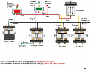
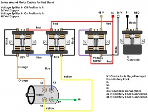
I am using three single pole double throw contactors and two single pole single throw contactors. For activation I am using two single pole single throw switches and one single pole double throw switch.
Here is the sequence of activation. I have installed a 36 volt lead into the contactor and a 48 volt positive lead. Then on the negative side I connected direct to a single pole single throw contactor. By doing a connect to negative that way, it allows me to open the circuit so disconnections can be done without the dreaded sparks. I added a voltage selector switch and an activation switch. By activating the voltage splitter contactor the appropriate voltage can be selected. I also added a light that indicates the system is activated and also discharges the controller at shutdown. Just use a 48 volt bulb in a taillight. Notice the activation circuit remains at 48 volts so only 48 volt contactors are used. Wire colors are your choice I just chose what was available at the moment. It is recommended to use a flexible 6 gauge cable set. All activation wiring can be 18 gauge. A single pole single throw contactor can be added for shorting the armature so full stall current can be seen. Or use a mechanical brake system to apply a load. Everything is dependent on how elaborate you want to be. Sometimes simplicity is the best way. A word about safety, be sure to wear eye protection and pay attention to voltage potentials as high voltage and current can burn skin really bad!
Note: input voltage to KSI circuit is wired to the Voltage Splitter for correct KSI input. As you wire the system make sure you do that. It matters in terms of controller activation some controllers will not activate if the wrong voltage is seen at the KSI input.


