QUESTION:
T Z from Colorado asked:
I still do not understand solenoid testing? I put 3 on and it still will not run
 ANSWER:
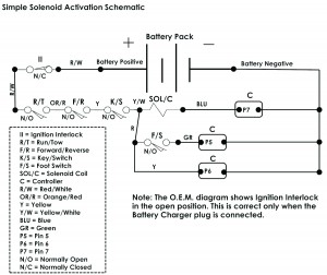
Continuing on, a solenoid (contactor, relay, whatever you choose to call it) does one thing and one thing only: It opens and closes a circuit by electrical activation. They are either a single pole double throw or single pole single throw in the golf car market. How the solenoid is activated is the key to troubleshooting. Again, that activation is only related to the small terminals. As I was saying in part one, some systems receive activation potentials from the controller. It is imperative you have the correct wiring diagram for the system you are testing. A simple example I can use is an E-Z-GO Direct Drive Control system (DCS). When you look at the wiring diagram for this system you can plainly see where the positive potential comes from. This is a very simplistic system and notice you have four colors of wire connected to the solenoid (YEL/WHT, RED, BLUE and YEL). Yellow/White, Yellow, and Red are connected together on one terminal and the Blue wire is connected to the opposite terminal. Notice the three Y, Y/W, and R are a positive potential. Positive is delivered from the ignition interlock switch to run/tow switch, directional switch, key switch, solenoid, accelerator switch and pin 6 on the controller. With R/T, F/R, K, in the closed position you should read battery positive on the solenoid. Before closing the accelerator switch (foot switch) you will read battery positive voltage on both terminals. If you do not the coil is open (replace the solenoid). If you do not read positive voltage on either terminal you have an open on the positive circuit we just talked about. You must go back to the start of that positive circuit and confirm positive voltage from the first connection point which is the ignition interlock switch. Next confirm positive voltage at the R/T switch, key switch, and F/R switch. Repair or replace the appropriate part (or wire) that has the open. This testing is done by connecting a voltmeter negative test lead wire to battery number 6 negative terminal (or B- on controller). Select a 50 volt DC scale and place the voltmeter positive test lead wire to each point we just talked about. Do not forget to confirm battery positive with the F/S closed at pin 6 on controller.
At this point the only thing missing is how we get battery negative to the solenoid. Look at the wiring diagram there is a blue wire connected to the solenoid small terminal opposite of the positive terminal. This blue wire connection is the negative connection input from the controller. Notice it is from the controller! Connect a voltmeter black lead wire to the blue wire connection on the solenoid. Connect the red voltmeter lead wire to battery number one positive terminal (or solenoid main positive from battery number one to large solenoid terminal). Activate the system, meaning key on, R/T in the run position, F/R in forward and the accelerator activated. You should read full system voltage. If you do not you are not receiving battery negative from the controller. Now what you do next is confirm all input voltages to the controller at pins 1 through 10. If they are correct replace the controller.
So far this is a very simple thing to do. However, with some systems being used by different car manufacturers it is a tad more complicated. That is why it is so important to have the correct diagram for the system being used in the car. You will use the same procedure as we just used. Don’t always assume you have a defective controller, confirm voltage inputs first. The cost of freight is high so make of things before ordering replacement parts.


