By: Matt Vallez
This article first appeared in September /October, 2004 issue of Golf Car News magazine, it has been updated, fact checked and reprinted for this issue.
Over the last few years dealers have been “beefing-up” their electric golf cars. It started with a motor or field coil change, then the controllers. Then the motors started to get even larger, and this meant larger, higher amp controllers. It soon became necessary to have 4-gauge wire to put it all together so nothing would melt.
All these modifications allow, or require higher amperage to flow through the power wiring to the primary electric components. The problem is that one part is often overlooked during this “beefing-up” process, the F&R switch.
I was speaking to the brains behind EV Parts Inc. Roderick Wilde and discussing the interesting things he has done with electric cars, mostly for racing purposes, (go to: www.suckamps.com) to come up with a hot topic for this months article. He and I both agreed that the F&R switch is the most overlooked part when “beefing-up” an electric car. Although this is not as exciting as modifying an electric postal jeep to reach speeds of over 100 MPH, it is a hot topic, literally.
Cars are often modified with the stock F&R switch unchanged except to connect a smaller gauge or thicker power wires to them. This is unacceptable and will only cause problems somewhere down the line. A mechanical F&R switch has a hard enough job as it is. It is always “on” so to speak; current is always passing through it. Your F&R switch is a circuit between the controller and your motor, and they must be capable of the same amp load. Once the switch is shifted from one direction to the other, it first passes through a natural point, so as not to arc before reversing the polarity to the field coils. Otherwise the load is constant.
These switches were designed to handle the stock amps, not the new level. Think about it, you just installed a 500-amp controller, this means that if required, your controller will send 500-amps to the motor, and that means 500 amps right through your F&R switch. The original system is capable of handling about a 350-amp peak, if that.
There are two good solutions that I know of. The simplest and least expensive is to modify a stock F&R switch to handle the load. The weakest part of these switches is the buss bars. On an E-Z-GO switch they are between the contacts on the cam, or part that moves.
These buss bars are thin and not made to carry large amps. Just replace them with some 3/16 inch thick by ½ inch wide copper bar and you’re off to the races.
The second alternative is more complex and more expensive. It requires replacing the mechanical switch with two, six terminal solenoids and a three-position control switch. For the solenoids, use two Nivel #1165 for 36-volt or Nivel #1130, both of these are rated at 200-amp continuous and 600 amp peak. This will work for most applications. As this is a more complicated set up I have made up a diagram to help.
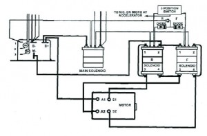 Next time you are making a “beefed-up” electric car remember the F&R Switch. Because your “beefed-up” electric car is only as good as its weakest part, so make sure that’s not the F&R switch. Nivel now manufactures a line of F&R switches for high amp applications. Ask your Nivel salesperson for more information.


